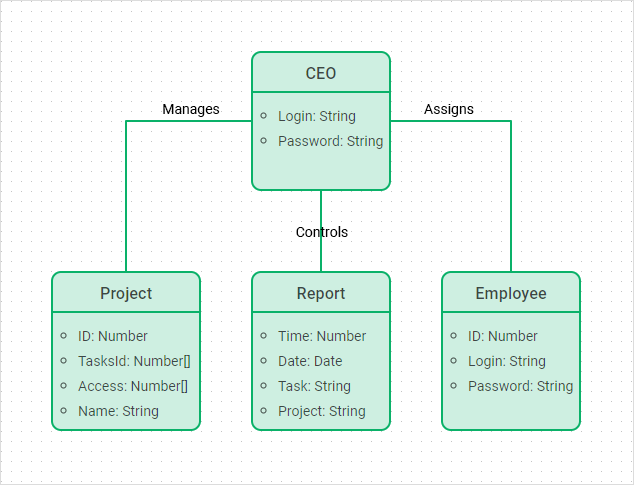
20+ uml requirements diagram
Another UML diagram type that can serve as a requirements gathering technique is the sequence diagram. UML guides the creation of multiple types of diagrams such as interaction structure and behaviour diagrams.
1
Functional requirements are captured in the use-case model to describe the interactions between the system and its environment users other systems.

. Use case diagram UML use case diagram. Click on the template to edit it online Requirement Gathering Templates Sequence Diagrams. Supports following UML diagrams.
It helps in analyzing and elaborating project requirements. UML 2x renamed statechart diagrams to state machine diagrams. Though there are 14 different types of UML diagrams for modeling applications developers use only three or four to document a software system.
Shows interactions between two or more processes using more than one pool. Association Class and Self Association. 2 UML 2 for systems engineering applications in 2003.
Visio is a part of the Microsoft family which is a diagramming software. Jira Requirementscc Excel Word. Use case diagram Sequence diagram Collaboration diagram Class diagram Statechart diagram Activity diagram Component diagram Deployment diagram and Package diagram.
Capture the increasingly complex flow of information through a system with a data flow diagram. A sequence diagram is the most commonly used interaction diagram. UML 2x has increased the number of diagrams from 9 to 13.
Timing diagram communication diagram interaction overview diagram and composite structure diagram. This is the next installment in a series of articles about the essential diagrams used within the Unified Modeling Language or UML. It permits you to specify and generate code in C.
However you can do it without buying any third-party tool just using some existing Java-based. A sequence diagram illustrates how the different parts of a system interact with each other to carry out a function and the order in which the interactions. GoF Design Patterns - Strategy.
The four diagrams that were added are. UML incorporates the current best practices in Object-Oriented modeling techniques. Developers and engineers use these diagrams as a framework to support their work in many ways.
GoF Design Patterns - Memento. Provide structure before coding begins Visualize requirements as you build on existing work. Subsequently the Object Management Group OMG adopted a version of SysML as.
SQL Server database developers seem reluctant to use diagrams when documenting their databases. A use case diagram is a graphic depiction of the interactions among the elements of a system. It shows a group of related message exchanges in a business.
It is probably because it has in the past been difficult to automatically draw precisely what you want other than a vast Entity-relationship diagram. BOUML is a UML diagram designer which is programmed in Qt and C. With the help of a data flow diagram your software team can.
Therefore all functional requirements should be implementation-neutral. What this implies is that you need to know just 20 of the UML language to explain 80 of your modeling needs. It outperforms in the real-time embedded agile engineering environment.
Unified Modelling Language UML is a modeling language in the field of software engineering which aims to set standard ways to visualize the design of a system. 2002-06-20 2020-07-23 v162 No Commercial Free Community Edition Java C WhiteStarUML. While a use case itself might drill into a lot of detail about every possibility a use-case diagram can help provide a higher-level view of the system.
Class diagrams sequence diagrams and use case diagrams remain the most in vogue. UML 2x added the ability to decompose software system into components and sub. Learn about UML BPMN ArchiMate Flowchart Mind Map ERD DFD SWOT PEST Value Chain and more.
Due to their simplistic nature use case diagrams can be a good communication tool for stakeholdersThe drawings attempt to mimic. Basic object-oriented programming OOP concepts are required to attempt the course. It has been said before that Use case diagrams are the blueprints for your system.
As we noted earlier an SRD is not a design document. It does not and should not define how the functional requirements must be implemented from a design standpoint. All combinations of pools processes and choreography may be used in a collaboration diagram.
In other words requirements should state what the system should do but not how it should do it. In my previous article on sequence diagrams I shifted focus away from the UML 14 spec to OMGs Adopted 20 Draft Specification of UML UML 2In this article I will discuss Structure Diagrams which is a new diagram. In general this is a simplified version of a collaboration diagram.

Uml Class Diagram Presenting A Simplified View Of The Model Download Scientific Diagram

The Uml Class Diagram Of The Floor Model Download Scientific Diagram

10 Javascript Libraries To Draw Your Own Diagrams Data Dashboard Javascript Art Journal Prompts

Free Editable Workflow Uml Diagram Edrawmax Time Diagram Sequence Diagram Activity Diagram

Uml Class Diagram Shows The Design Of The Proposed Internal Structure Download Scientific Diagram
1
The Class Diagram In The Unified Modeling Language Uml The Green Download Scientific Diagram

Class Diagram For Sale System Download Scientific Diagram

Simplified Unified Modeling Language Uml Diagram Showing The Download Scientific Diagram

How To Create A Javascript Uml Class Diagram Dhtmlx Diagram Library

Requirement Uml Class Diagram Download Scientific Diagram

Uml Class Diagram Representing Data Structure Download Scientific Diagram

Management System Use Case Use Case Diagram Component Diagram

Scrapy Kafka Elk Redis Diagram Architecture Diagram Topics

Unified Modelling Language Uml Class Diagram Of Entities In The Download Scientific Diagram
Uber Class
1